新能源汽车电动机驱动系统综述
电动机驱动控制系统是新能源汽车车辆行使中的主要执行结构,驱动电动机及其控制系统是新能源汽车的核心部件(电池、电动机、电控)之一,其驱动特性直接决定汽车行驶的爬坡、加速、最高速度等主要性能指标,是电动汽车的重要部件。
1、新能源汽车电动机驱动系统概述
新能源汽车驱动系统包括电动机和电子控制器,电池是其能量供给单元。
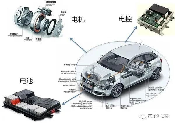
新能源汽车电动机驱动系统
控制器主要由功率模块(电源的电子开关线路)和控制模块(包括微处理器和相应软件)组成,控制器的作用是将动力源的电能转变为适合于电动机运行的另一种形式的电能,控制器本质上是一个电能变换控制装置。控制器选择恰当时,驱动系统的性能取决于电动机。
电动机是把电能转换成机械能的装置。它被广泛应用于机械、冶金、石油、煤炭、化工、航空、交通、农业等各种行业。
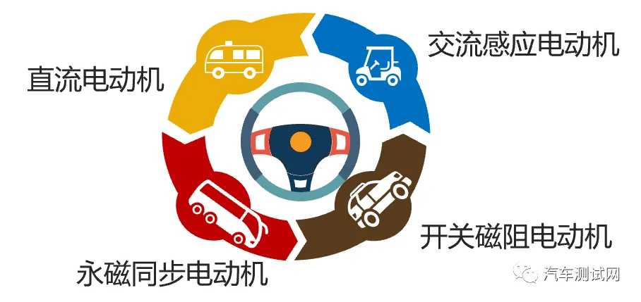
电动机应用场景
常见的电动机分类及其种类如下:
-
功能分类:驱动电动机和控制电动机(包括步进、测速、伺服、自整角电动机等)。
-
电动机的转速与电网电源频率之间的关系分类:同步电动机和异步电动机。
-
最高转速分类:最高转速小于6000r/ min 的普通电动机和最高转速高于6000r/ min 的高速电动机。
-
电源相数分类:单相电动机和三相电动机。
-
按防护类型分类:电动机可分为开启式、防护式、封闭式、隔爆式、防水式和潜水式电动机。
-
安装结构分类:卧式、立式、带底脚式、带凸缘式电动机。
-
绝缘等级分类:E级、B级、F级、H级等。
-
电能种类分类:直流电动机和交流电动机(方波电动机和正弦波电动机)。
常见的电动机中适用于电力驱动的电动机的分类见下表:
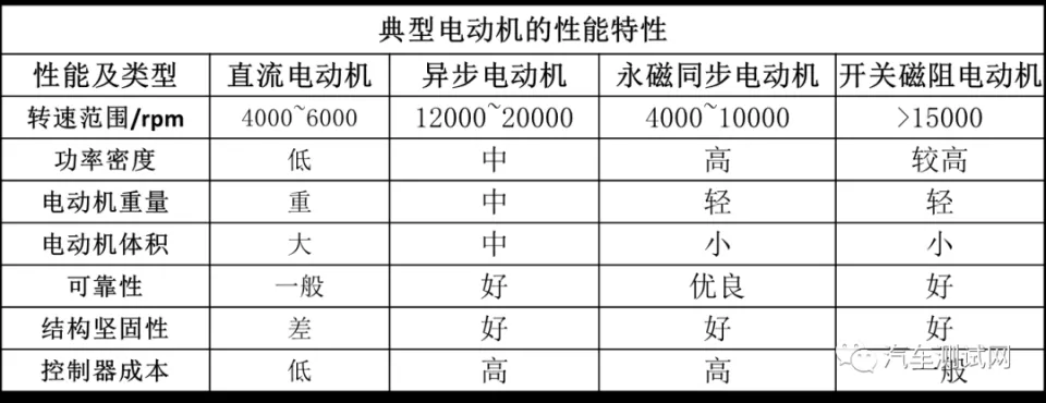
电动机性能类型分类表
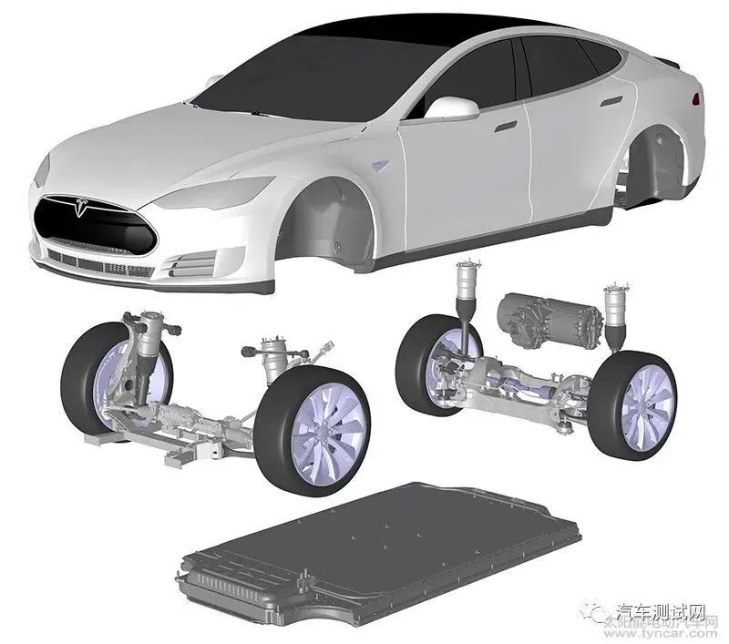
新能源动力汽车的特点是将不同类型的能源转换为电能,电动机将电能转换为机械能,并通过传动系统将机械能传递到车轮驱动车辆行驶,电动机在动力系统中的位置如下图所示。

新能源汽车电动机的位置示意图
①纯电动汽车对电动机的要求
电动汽车对电动机的要求是功率和转矩应满足电动车辆动力性能的要求,适应车辆频繁的起动、加速、制动减速和倒车的运动要求;一般要求电动机能承受2~4倍的过载,并能实现四象限的运转和高效回收车辆在制动是的反馈能量;电动机工作电压高、转速高可以提高电动机的比功率,减小电动机的尺寸、降低重量和有利于在车辆上的安装布置;电动机具有良好的可靠性、耐温、耐湿,结构简单维修方便。
纯电动汽车结构示意图
②混合动力汽车对电动机的要求
混合动力汽车对电动机的要求是电动机可单独驱动汽车行驶,在市区实现零排放。电动机在汽车启动、加速、大负荷运行时可以与发动机共同驱动汽车,在减速制动时以再生模式工作,起回收制动能量作用,与发电动机功能相同。
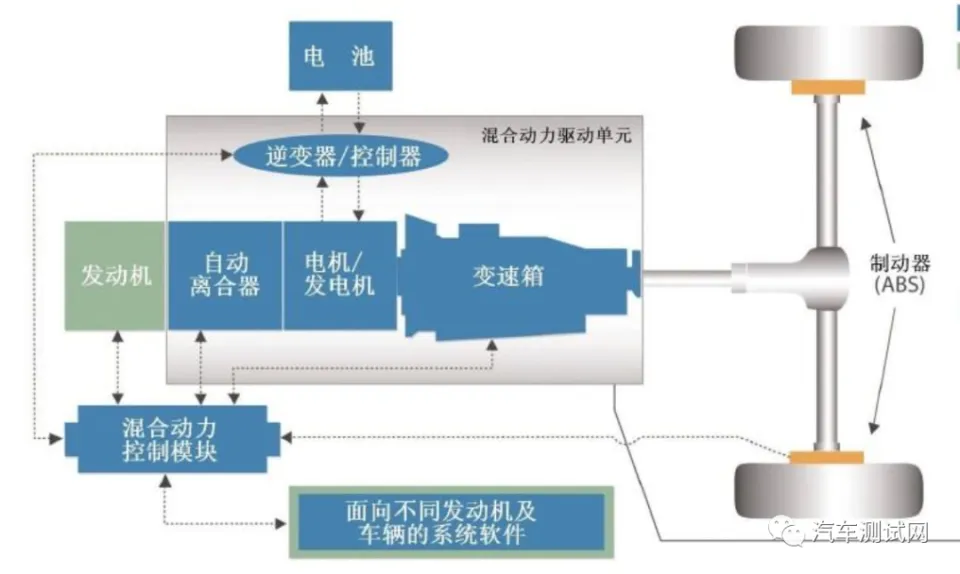
混合动力汽车结构示意图
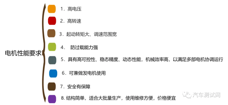
电动机性能要求汇总
2、直流电动机
直流电动机分为定子与转子,定子和转子之间由空气隙分开。定子包括主磁极,机座,换向极,电刷装置等。转子包括电枢铁芯,电枢绕组,换向器,轴和风扇等。
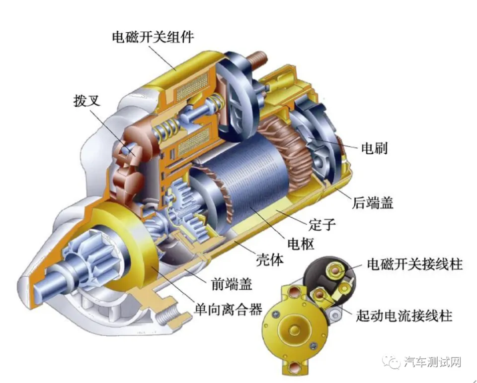
直流电动机结构示意图
-
定子:发动机中固定不动的部分,它主要由主磁极、机座和电刷装置组成。主磁极是由主磁极铁芯(极心和极掌)和励磁绕组组成,其作用时用来产生磁场。
-
转子:电动机的转动部分,主要由电枢和换向器组成。电枢是电动机中产生感应电动势的部分,主要包括电枢铁芯和电枢饶组。换向器又称整流子,使转动的电枢绕组得以同外电路连接起来,并实现将外部直流电流转化为电枢绕组内的交流电流。

转子结构示意图
直流电动机工作原理:直流电从两电刷之间通入电枢绕组,电枢电流方向如下图所示。由于换向片和电源固定联接,无论线圈怎样转动,总是N极有效边的电流方向向里,S极有效边的电流方向向外。电动机电枢绕组通电后受力(左手定则)按逆时针方向旋转。线圈在磁场中旋转将在线圈中产生感应电动势,由右手定则,感应电动势的方向与电流的方向相反,也称为反电动势。虽然电流方向使交替变化,但线圈所受电磁力的方向不改变,因而线圈可以连续地按逆时针方向旋转。
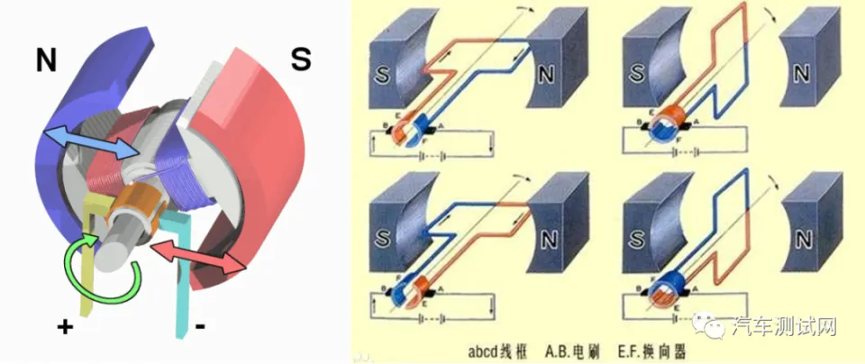
直流电动机工作原理图
3、三相异步感应电动机
三相异步感应电动机(Three-Phase Induction Motor)是一种常见的电动机类型,广泛用于工业和商业应用中。它是一种非同步电动机,因为其转子的运动速度略低于旋转磁场的速度,因此被称为"异步"电动机。
三相异步电动机的结构如下图所示,主要由定子、转子、机座、支架、外壳、风扇罩和冷却风扇等组成。感应式电动机转子与定子之间没有任何电气上的联系,能量的传递全靠电磁感应作用。
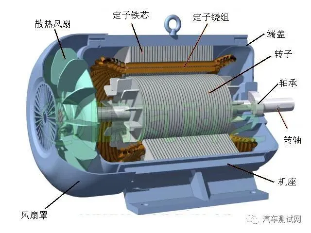
三相异步电动机
①绕组旋转磁场的产生
假定三相异步电动机定子绕组的连接方法为星形连接,单个绕组的始端分别为ABC;末端分别为XYZ。三相对称绕组分别为AX、BY、CZ并接在三相正弦交流电源上,通入三相交变电流。
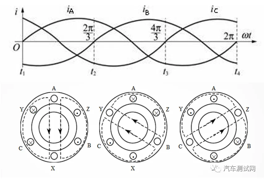
三相交流电波形与在定子绕线形成测旋转磁场
一般规定,电流为正值时从绕组的始端流入(A、B、C端),从绕组的末端流出(X、Y、Z);为负值时相反。据此规则,可得到三相电流产生的磁场随时间变化的关系。
②异步电动机旋转磁场的转向
异步电动机的旋转方向与通入绕组的三相交流电相序有关。任意对调两根三相电源街道定子绕组上的导线,就可以改变异步电动机的旋转方向。
③异步电动机的工作原理
三相异步感应电动机的工作原理基于法拉第的感应定律。当交流电流通过定子的三个绕组时,会产生一个旋转磁场。由于旋转磁场不断切割转子中的闭合导体,产生感应电动势和感应电流,再由转子中的感应电流和旋转磁场的相互作用产生电磁转矩,使得转子随着旋转磁场的方向同向运转。在异步电动机中,为保持旋转磁场始终切割转子导体产生感应电流,转子转速小于旋转磁场的速度。

笼型异步电动机转子绕组电流方向
4、永磁同步电动机
永磁同步电动机(Permanent Magnet Synchronous Motor,PMSM)是一种常见的电动机类型,广泛用于新能源汽车、工业应用、家用电器等领域。与其他类型的电动机相比,PMSM在效率、功率密度和动态性能方面具有优势。
PMSM的核心是永磁体,通常是强磁性材料(如永磁铁矿物)制成。在PMSM中,永磁体产生一个固定的磁场,而电流通过电动机的绕组产生一个旋转磁场。这两个磁场之间的相互作用导致电动机的旋转运动。
PMSM通常与一个控制系统配合使用,控制系统监测电动机的状态(例如电流、速度、位置)并根据需要调整电流来控制电动机的运行。这种精确的控制使得PMSM可以在各种负载条件下提供高性能。
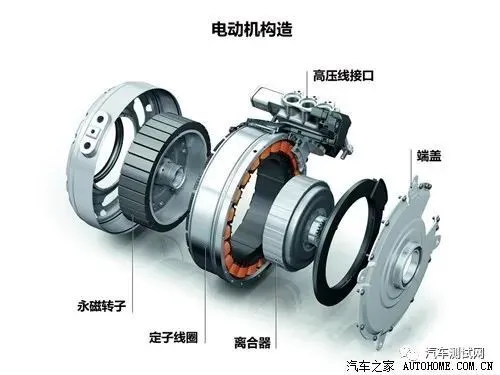
混合动力汽车永磁同步电动机分解结构
5、磁阻电动机
磁阻电动机(Reluctance Motor)工作原理基于磁阻力,而不是永磁或电磁感应,通常不需要永磁体或电磁绕组,因此在某些应用中具有高可靠性等优势。
磁阻电动机利用转子磁阻不均匀而产生转矩的小功率同步电动机,又称反应式同步电动机。它不依靠定、转子绕组电流所产生磁场的相互作用而产生转矩,而是依靠“磁阻最小原理”产生转矩。
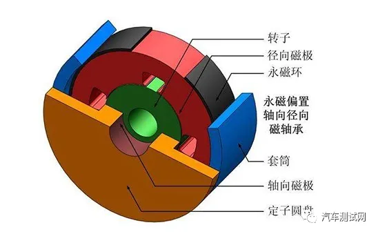
开关磁阻电动机结构
磁阻电动机的工作原理基于磁阻力或磁阻效应。这种效应利用了磁场中磁路的不同磁导率(磁阻)会导致磁场线路更容易通过具有较低磁导率的区域,而在具有较高磁导率的区域中更难通过的事实。电动机的转子通常具有一些不同形状的铁芯,这些铁芯可以通过控制电流来调整磁场的分布,从而导致转子发生旋转。
磁阻电动机的应用范围相对有限,主要用于特定的高温和高可靠性应用,例如空间探测器、核电站等。
总而言之,新能源汽车的驱动系统依赖于电动技术,与传统内燃机车辆有很大的不同,新能源汽车的发展正在不断推动电动技术和电池技术的进步。新能源汽车电驱动系统的研究具有重要意义,它不仅能够推动汽车产业向可持续、低碳方向发展,减少对有限化石燃料的依赖,还有助于减少环境污染和气候变化的影响。
The electric motor drive control system is the main execution structure in the operation of new energy vehicles. The drive electric motor and its control system are one of the core components (battery, electric motor, electronic control) of new energy vehicles. Its driving characteristics directly determine the main performance indicators such as climbing, acceleration, and maximum speed of the vehicle, and are important components of electric vehicles.
1. Overview of Electric Motor Drive System for New Energy Vehicles
The drive system of new energy vehicles includes an electric motor and an electronic controller, with the battery as its energy supply unit.
New energy vehicle electric motor drive system
The controller is mainly composed of a power module (electronic switch circuit of the power supply) and a control module (including a microprocessor and corresponding software). The function of the controller is to convert the electrical energy of the power source into another form of electrical energy suitable for the operation of the motor. The controller is essentially an electrical energy conversion control device. When the controller is selected appropriately, the performance of the drive system depends on the electric motor.
An electric motor is a device that converts electrical energy into mechanical energy. It is widely used in various industries such as machinery, metallurgy, petroleum, coal, chemical, aviation, transportation, agriculture, etc.
Application scenarios of electric motors
The common classifications and types of electric motors are as follows:
Functional classification: Drive motor and control motor (including stepper, speed measurement, servo, self-tuning motor, etc.).
Classification of the relationship between the speed of an electric motor and the frequency of the power grid: synchronous motor and asynchronous motor.
Classification of maximum speed: ordinary motors with a maximum speed less than 6000r/min and high-speed motors with a maximum speed greater than 6000r/min.
Power phase classification: single-phase motor and three-phase motor.
Classified by protection type: Electric motors can be divided into open type, protective type, enclosed type, explosion-proof type, waterproof type, and submersible type.
Installation structure classification: horizontal, vertical, with foot type, with flange type electric motor.
Insulation level classification: E level, B level, F level, H level, etc.
Classification of electric energy types: DC motors and AC motors (square wave motors and sine wave motors).
The classification of common electric motors suitable for electric drive is shown in the table below:
Classification Table of Motor Performance Types
The characteristic of new energy vehicles is to convert different types of energy into electrical energy. The electric motor converts electrical energy into mechanical energy and transmits it to the wheels through the transmission system to drive the vehicle. The position of the electric motor in the power system is shown in the following figure.
Location diagram of electric motor for new energy vehicles
① Requirements for electric motors in pure electric vehicles
The requirements for electric motors in electric vehicles are that the power and torque should meet the power performance requirements of the electric vehicle, and adapt to the frequent starting, acceleration, braking, deceleration, and reversing motion requirements of the vehicle; Generally, it is required that the electric motor can withstand 2-4 times the overload, and can operate in four quadrants and efficiently recover the feedback energy of the vehicle during braking; High operating voltage and speed of electric motors can increase their specific power, reduce their size and weight, and facilitate their installation and layout on vehicles; Electric motors have good reliability, temperature and humidity resistance, simple structure, and easy maintenance.
Schematic diagram of pure electric vehicle structure
② Requirements for electric motors in hybrid vehicles
The requirement for hybrid vehicles is that the electric motor can drive the vehicle independently and achieve zero emissions in urban areas. The electric motor can work together with the engine to drive the car during start-up, acceleration, and high load operation. It operates in regenerative mode during deceleration and braking to recover braking energy, and has the same function as the generator motor.
Schematic diagram of hybrid vehicle structure
Summary of Performance Requirements for Electric Motors
2. DC motor
DC motors are divided into stator and rotor, separated by an air gap between them. The stator includes the main magnetic pole, machine base, reversing pole, electric brush device, etc. The rotor includes armature core, armature winding, commutator, shaft, and fan, etc.
Schematic diagram of DC motor structure
Stator: The fixed and immovable part of an engine, mainly composed of the main magnetic pole, base, and electric brush device. The main magnetic pole is composed of the main magnetic pole core (pole center and pole palm) and the excitation winding, which is used to generate a magnetic field during operation.
Rotor: The rotating part of an electric motor, mainly composed of an armature and a commutator. The armature is the part of an electric motor that generates induced electromotive force, mainly consisting of the armature core and armature coil assembly. A commutator, also known as a commutator, connects the rotating armature winding to an external circuit and converts external DC current into AC current inside the armature winding.
Schematic diagram of rotor structure
Working principle of DC motor: DC current flows into the armature winding between two brushes, and the direction of armature current is shown in the following figure. Due to the fixed connection between the commutator and the power supply, no matter how the coil rotates, the current direction of the effective side of the N pole always moves inward, and the current direction of the effective side of the S pole always moves outward. After the armature winding of the electric motor is energized, it rotates counterclockwise under force (left-hand rule). The rotation of a coil in a magnetic field will generate an induced electromotive force in the coil. According to the right-hand rule, the direction of the induced electromotive force is opposite to the direction of the current, also known as the back electromotive force. Although the direction of the current alternates, the direction of the electromagnetic force acting on the coil does not change, so the coil can continuously rotate counterclockwise.
Working principle diagram of DC motor
3. Three phase asynchronous induction motor
Three Phase Induction Motor is a common type of electric motor widely used in industrial and commercial applications. It is a asynchronous motor because the speed of its rotor is slightly lower than the speed of the rotating magnetic field, hence it is called an "asynchronous" motor.
The structure of a three-phase asynchronous motor is shown in the following figure, mainly composed of stator, rotor, base, bracket, housing, fan cover, and cooling fan. There is no electrical connection between the rotor and stator of an induction motor, and energy transmission relies entirely on electromagnetic induction.
Three phase asynchronous motor
① Generation of Rotating Magnetic Field in Winding
Assuming that the connection method of the stator winding of a three-phase asynchronous motor is star connection, and the starting ends of each individual winding are ABC; The ends are XYZ. The three-phase symmetrical windings AX, BY, CZ are connected in parallel to a three-phase sinusoidal AC power supply, and a three-phase alternating current is applied.
The waveform of three-phase alternating current and the formation of a rotating magnetic field in the stator winding
Generally, when the current is positive, it flows from the beginning of the winding (A, B, C terminals) and flows out from the end of the winding (X, Y, Z); When it is negative, it is the opposite. According to this rule, the relationship between the magnetic field generated by three-phase current and time can be obtained.
② Direction of Rotating Magnetic Field in Asynchronous Motor
The rotation direction of an asynchronous motor is related to the phase sequence of the three-phase AC current passing through the winding. By arbitrarily swapping the wires on the stator winding of two three-phase power sources, the rotation direction of the asynchronous motor can be changed.
③ Working principle of asynchronous motor
The working principle of three-phase asynchronous induction motor is based on Faraday's law of induction. When AC current passes through the three windings of the stator, a rotating magnetic field is generated. Due to the continuous cutting of closed conductors in the rotor by the rotating magnetic field, induced electromotive force and induced current are generated. Then, the interaction between the induced current in the rotor and the rotating magnetic field generates electromagnetic torque, causing the rotor to rotate in the same direction as the rotating magnetic field. In asynchronous motors, in order to maintain a rotating magnetic field that always cuts the rotor conductor and generates induced current, the rotor speed is lower than the speed of the rotating magnetic field.
Current direction of rotor winding in cage asynchronous motor
4. Permanent magnet synchronous motor
Permanent Magnet Synchronous Motor (PMSM) is a common type of electric motor widely used in fields such as new energy vehicles, industrial applications, and household appliances. Compared with other types of electric motors, PMSM has advantages in efficiency, power density, and dynamic performance.
The core of PMSM is a permanent magnet, usually made of strong magnetic materials such as permanent magnet minerals. In PMSM, the permanent magnet generates a fixed magnetic field, while the current passing through the winding of the motor generates a rotating magnetic field. The interaction between these two magnetic fields causes the rotational motion of the electric motor.
PMSM is usually used in conjunction with a control system that monitors the status of the motor (such as current, speed, position) and adjusts the current as needed to control the operation of the motor. This precise control enables PMSM to provide high performance under various load conditions.
Decomposition structure of hybrid electric vehicle permanent magnet synchronous motor
5. Reluctance motor
The working principle of a reluctance motor is based on magnetic resistance, rather than permanent magnets or electromagnetic induction. It usually does not require permanent magnets or electromagnetic windings, and therefore has advantages such as high reliability in certain applications.
Reluctance motor is a low-power synchronous motor that generates torque by utilizing uneven rotor reluctance, also known as reactive synchronous motor. It does not rely on the interaction between the magnetic fields generated by the stator and rotor winding currents to generate torque, but relies on the principle of "minimum magnetic resistance" to generate torque.
Structure of Switched Reluctance Motor
The working principle of a reluctance motor is based on magnetic resistance or reluctance effect. This effect takes advantage of the fact that the different magnetic permeability (reluctance) of the magnetic circuit in a magnetic field makes it easier for magnetic field lines to pass through areas with lower permeability, while it is more difficult to pass through areas with higher permeability. The rotor of an electric motor usually has iron cores of different shapes, which can adjust the distribution of the magnetic field by controlling the current, causing the rotor to rotate.
The application range of reluctance motors is relatively limited, mainly used for specific high-temperature and high reliability applications, such as space probes, nuclear power plants, etc.
In summary, the drive system of new energy vehicles relies on electric technology, which is significantly different from traditional internal combustion engine vehicles. The development of new energy vehicles is constantly driving advances in electric and battery technology. The research on electric drive systems for new energy vehicles is of great significance. It can not only promote the sustainable and low-carbon development of the automotive industry, reduce dependence on limited fossil fuels, but also help reduce environmental pollution and the impact of climate change.

